In the last post we talked about the CPU module and what it should accomplish, as well as some strategies to debug and put together the module. In this post, I will discuss the graphics subsystem.
What is the Graphics Subsystem?
The graphics part of the game, is a subsystem of the overall board that is responsible for independently rendering graphics to the screen. Graphics, consists of routines to fetch color or tile data, calculate the position of where those things should go, and write them to the screen. Note, in an FPGA, it should be doing this as an independent subsystem, meaning that while the CPU is going, graphics should be reading from sources the CPU is constantly writing to (ie. memory) and performing work to write pixels to the screen. How it does this, can be very simple or very complex depending on the board you are working with. But, basically the idea is that the CPU program determines what should be on the screen each frame, and writes data to memory. The graphics subsystem reads from these locations and then performs its work to draw those things on screen.
Layers and Tiles
Most pixel based graphics you will work with consist of layers and tiles. Tiles are square in nature, and can be of many sizes. In the Raizing system, all tiles are 8×8 pixels in dimension. Sure, there can be larger graphics such as bosses or backgrounds, but the basic building block is 8×8. From 8×8 tiles, the program writes to memory how many 8×8 tiles span the entirety of the graphic length and width wise for object (or commonly called sprite) graphics.
There are different layers usually in a tile graphics system. The most common and basic are scroll layers and object layers. The Raizing system also has a dedicated text layer that is a scrollable tile layer which is used for placement of HUD elements and general text. These layers, are used to draw various graphics in a certain priority which determines which should float over one another. A lot of the time, tile graphics systems consist of multiple scroll layers, not just one. These can be used to create effects such as foreshadowing or parallax scrolling where one scroll layer moves at a faster rate than another, thereby creating the illusion of depth:
In the Raizing system, there are 3 scroll layers: Background, Foreground and Text. There is an object layer that contains sprites, and finally an “extra text” layer that always floats on top of everything else, no matter what.
Scroll Layers
The scroll layers each have their own independent area of ram that the CPU writes to. It is a block of 0x1000 bytes each, which comprise 0x3000 bytes for scroll data. Furthermore, there is a concept of a local and global priority. So, within each scroll layer, each tile has its own priority level weighed against other tiles for the same layer. Secondly, there is also a priority level that is weighed against other tiles in other layers to determine the one that should be on top.
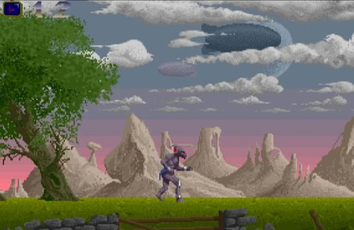
Take for example a typical scene in Batrider in level 1 where the character goes under a bridge to enter Manhattan:
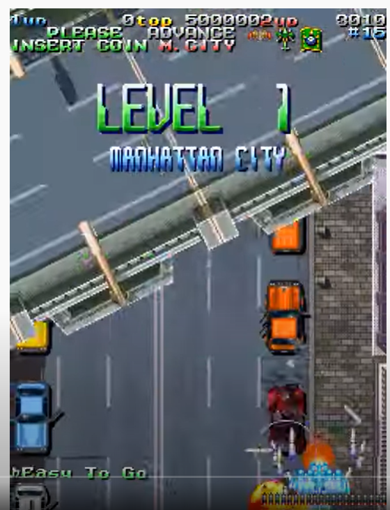
So you see the bridge, and the cars, and the player character? The player should be over the cars, and then the road is apart of the background scroll layer, so the player should be over that too. The bridge that floats should be above the player and other layers, so to create the effect of the player going under the bridge and being obstructed for a couple frames. The cars, player and bullets are apart of the object layer, the road is the background layer, and then the other parts are foreground. The text and HUD elements are apart of the extra text layer. Understanding where the different graphics on screen come from is essential to debugging issues and drawing things properly from a functional perspective.
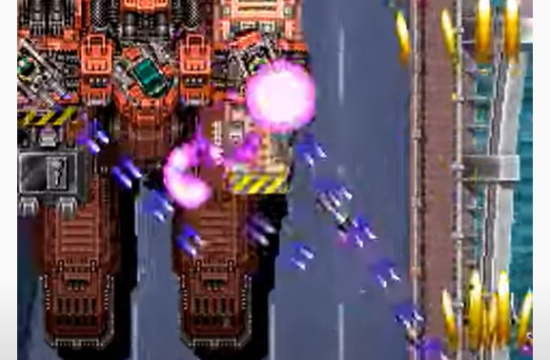
Interestingly enough, the bosses in the game are composed of scroll and object parts:
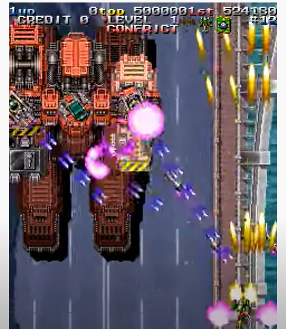
Taking a look at this boss, you would think the entirety of it is made up of objects. But, that’s not true. In fact, only the gun turrets mounted on top and the middle tier that houses them are objects. The rest of the boss, is in fact a scroll layer that moves back and forth, and the objects are calculated to follow suit. This fact becomes important again when debugging issues that might occur and thinking about the priority of the different graphics in relation to each other.
Objects (Sprites)
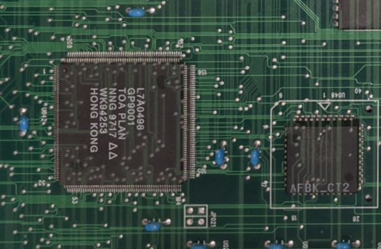
Sprites also have an independent section of RAM that the CPU performs writes to that is about 0x800 bytes in length and mirrored. The parts of the graphics subsystem that perform the rendering of the object and scroll layers are done by the GP9001 chip. So, the chip has pins that have a direct line to all this memory that’s shared with the CPU, and performs work per frame.
Objects are fairly complex in the Raizing system. There can be a maximum of 256 sprites total that can be on the screen at any given time, and each sprite entry takes up 8 bytes (64 bits). 8×256 is 2048, which corresponds to the exact length of the sprite ram, 0x800, as discussed above. Objects are a scrollable tile layer, but what’s interesting is that the tiles, can be anywhere on the screen at any given time. This is not like a wall of 8×8 tiles one after the other like the scroll layers, but rather, various objects that can appear on top of each other, in random parts, or pretty much anywhere. Each object has a priority level locally, and also globally, as they are weighed against other scroll layers, so this must be evaluated as well.
Extra Text
The extra text layer, is actually not apart of the GP9001, and it has no part in any of its rendering activity. It is a layer that’s drawn by the CPU, and is a scrollable tile layer that is similar to the scroll layers, only this layer always is on top, and is used for HUD elements and text, as mentioned. Sometimes its used for different text effects and that sort of thing, but generally HUD and text/ small graphics in general.
Video Timings
Up until now, I have been introducing you to the background of the graphics subsystem to get you used to the concepts (well, the interesting parts anyway). Seeing what’s going on in the screen, and breaking down the various components you see is very important. However, from a technical perspective, that’s not the most important thing in the system. That’s the final result of what the player sees.
In fact, when you talk about graphics, you should first talk about the video timings. The video timings are what makes it possible to draw graphics and moving images on screen in the first place. Each board has different video timings. The video timings determine the pixel resolution, the refresh rate, and other parameters. I won’t go into the technicals of calculating these things, but rather just diagram out what happens and introduce you to some terminology and key points:
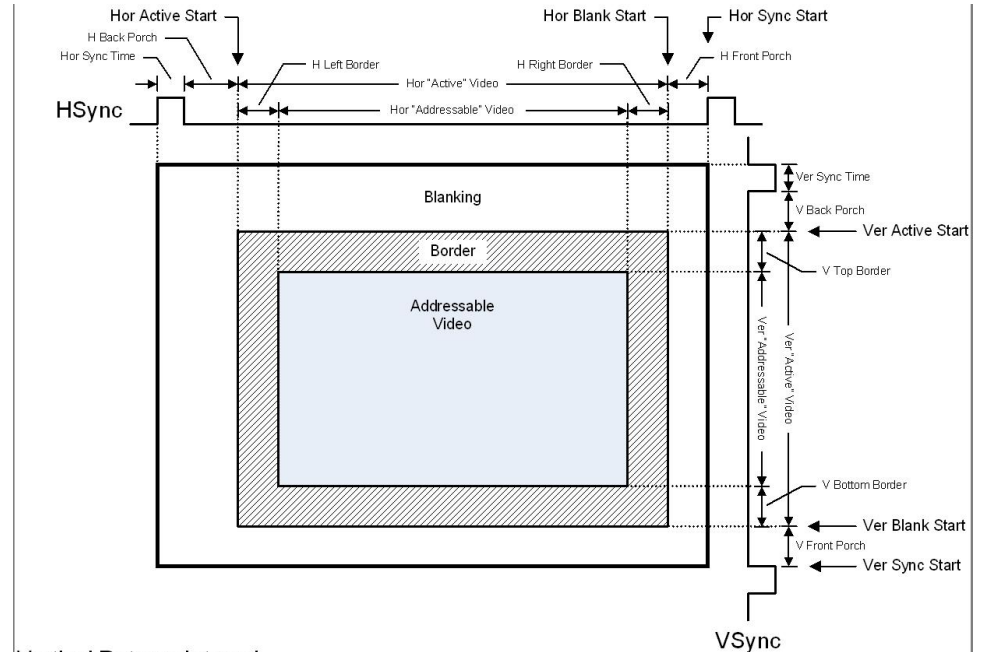
So, you see the part that says “Addressable Video” in the diagram? That’s the only thing of what the player sees when pixels are rendered on the screen. But, did you know there are other parts of video that are more important than that? These are the important concepts you need to know:
- The way a CRT works is that there is a beam goes from left to right, top to bottom, and then retraces all the way back up to the start, one horizontal line at a time.
- The beam though, is only active and shooting light in the addressable video space. The period where it isn’t, and is simply setting up for the next line is called the blanking period.
- This concept is very important in graphics. Since graphics are drawn one line at a time on the screen, this horizontal blanking period, is an opportunity to draw the pixels for the line that follows in a buffer such that when that beam arrives again in that addressable video space of the next line, it knows what pixels to draw.
- Vertical Blanking, on the other hand, is an opportunity to set up things for the frame that follows.
- So, what programs often do is they write all data necessary to render the following frame to graphics ram in the vblank period. In the hblank period, the renderer takes over and scans the data from the graphics ram to determine what to draw for each line.
- HSync and VSync shifts the image.
- Back Porch and Front Porch define areas before and after the addressable video space where blanking can occur. Sometimes, different boards divide their blanking space and do stuff before a line, after a line, or before and/or after the frame.
- Refresh Rate is calculated from these parameters, and determines how many frames are drawn to the screen per second. The lower the refresh rate, the more choppy the game may appear, and the higher the smoother.
- The pixel clock is the rate at which pixels are drawn to the screen at a time from the buffer.
So, with this basic information, let’s talk about how you can put together a graphics system in FPGA.
Putting it all Together
Let’s start with the video timings. These are very important because this is going to determine when your graphics code gets executed, and so from these timings, you can determine when things are setup, when to draw to the buffers, when to prepare for the next line, etc. For this, I use a module in JTFrame called vtimer, but it’s not hard to do one yourself from scratch to count lines according to a clock:
jtframe_vtimer #(
  .V_START(0),
  .VB_START(239),
  .VB_END(262),
  .VS_START(244),
  .VS_END(249),
  .HB_END(431),
  .HB_START(319),
  .HS_START(360),
  .HS_END(379)
) u_vtimer(
  .clk(clk96),
  .pxl_cen(pxl_cen),
  .LHBL(lhbl),
  .LVBL(lvbl),
  .HS(hsync),
  .VS(vsync),
  .H(hpos),
  .vdump(vpos),
  .vrender(vrender_o)
);
For the Raizing system, vertical lines start at 0 and go to 239. On line 240, that’s when the vblank period begins, and it ends on line 263. So in other words, there is a period of 23 lines where vblank occurs. The timing of each line here is related to the horizontal timing. horizontal lines start at 0 and go to 319. At line 320, that’s when the horizontal blanking period begins and goes to line 432. So, there is a horizontal blanking period of 112. So you can start to get a picture of the overall timings of the video now, and when you might do things. The module outputs tell you when sync is occurring, what line the beam is on, and if you are in blanking, etc. You read the outputs of this module, and do stuff. The stuff that you do, depends on how the logic for your board is and what is happening there. All boards have circuitry for a line counter that does precisely this, and the outputs tell the game program what to do when, which will in turn, correspond to the video output working properly and outputting colors on screen.
Next, you must write the different modules that scan the RAM the CPU program wrote to that tell you what graphics to draw on the screen, and where. To do this, you need to know the RAM format for the scroll, object and extra text layers and how to interpret them from a data perspective when you scan them.
Graphics RAM Formats (Raizing)
- Scroll
- Bits 15 to 0: Tile number
- Bits 22 to 16: Palette Color
- Bits 27 to 24: Priority Level
- Object
- Bits 3 to 0: Sprite Y Size (in # of tiles, add 1)
- Bits 15 to 7: Sprite Y Position (in pixels)
- Bits 19 to 16: Sprite X Size (in # of tiles, add 1)
- Bits 31 to 23: Sprite X Position (in pixels)
- Bits 49 to 32: Sprite Number
- Bits 55 to 50: Palette Color
- Bits 59 to 56: Priority Level
- Bit 60: Flip X
- Bit 61: Flip Y
- Bit 62: Multi-Connected Sprite (A sprite that’s a combination of other networked sprites)
- Bit 63: Sprite Active
- Extra Text (divided into Text RAM, Line Select and Line Scroll parts)
- Text RAM
- Bits 9 to 0: Tile Number
- Bits 15 to 10: Palette Color
- Line Select
- Bits 12 to 0: Line Select
- Bit 15: X Flip for Line
- Line Scroll
- Bit 8 to 0: X Scroll for Line
- Text RAM
Interpreting the Data
So, for each of the above, you are going to build independent modules that scan each of the RAM areas and interpret the data. This is called the scanning phase of the renderer. According to this design, you will have 3 different modules: scroll, object and extra text. The scroll, will of course, have 3 layers, so it will have 3 instances of the same renderer which scan the 3 different areas of scroll.
For the scroll and extra text layers, it is relatively simple to scan the ram, and do the next phase of the renderer, which is called queueing. Why? Well, because these layers are only flat tile layers where the tiles are situated one after the other in 8×8 blocks. So, you can do a linear scan and queue at the same time. Objects, on the other hand, are a bit more complicated.
For objects, since the requirement is that there are 256 sprites on any area of the screen, and no limit per scanline, you need to scan the RAM and only queue sprites that intersect the line which you are rendering for. So, you need a scanline intersection algorithm to do this, and basically that involves checking the y position of the sprite while you are scanning, and the y-size of the sprite, and seeing if that intersects the line you are currently rendering for.
All these renderers are state machines, essentially. There is a sequence of events where you scan a particular ram for contents, pull them out and interpret them, and then create another buffer where you are storing work to do. Then, the work to do essentially entails using the relevant tile number you got to pull the data from the graphics rom (and perhaps decode it), and then writing the data to a line buffer which includes not only the pixel data to be plotted, but the priority level of them so they can be weighed against other layers in a later step.
You can view my scroll renderer here: https://github.com/MiSTer-devel/Arcade-Raizing_MiSTer/blob/develop/modules/raizing_video/raizing_scroll.v#L299
You can view my object renderer here: https://github.com/MiSTer-devel/Arcade-Raizing_MiSTer/blob/develop/modules/raizing_video/raizing_obj.v#L22
Finally, you can view my extra text renderer here: https://github.com/MiSTer-devel/Arcade-Raizing_MiSTer/blob/develop/modules/raizing_video/raizing_extratext.v#L22
Each of these 3 renderers accomplishes the requirements above, and outputs data to line buffers that include the pixel data, and the priority level.
Mixing
After you’ve interpreted the data in the relevant graphics RAM areas and have the final pixels and priority level written to a line buffer, the next step is to pipe that data out to a mixer. What the mixer does is essentially take the individual pixel outputs for that particular pixel, determine what the final color should be for that pixel by using the priority levels that indicate what is on top, and then piping that out to the final step, palette lookup and color calculation.
How to do this mixing, varies for each board you are working on. Sometimes determining what layer’s pixel should be on top is a complicated thing, sometimes not. For this, I use a verilog combinational function to mix together the pixel outputs and determine priority:
function [10:0] pixel_priority_mux;
    input [4:0] pri;
    input [10:0] et;
    input [14:0] obj,scr2,scr1,scr0;
    begin
        pixel_priority_mux = blank_pixel;
        for(i=0;i<16;i=i+1) begin
            if(pri[0] && scr0[14:11] == i[3:0]) pixel_priority_mux = scr0[10:0];
            if(pri[1] && scr1[14:11] == i[3:0]) pixel_priority_mux = scr1[10:0];
            if(pri[2] && scr2[14:11] == i[3:0]) pixel_priority_mux = scr2[10:0];
            if(pri[3] && obj[14:11] == i[3:0]) pixel_priority_mux = obj[10:0];
        end

        if(pri[4]) pixel_priority_mux = et;
    end
endfunction
How this works is very simple. pixel_priority_mux is the final pixel value, and so I start with a blank pixel (palette location 0). There are 16 priority levels in the Raizing system, so I loop through all 16 and see if any of the layers’ pixels match the current iteration. If they do, I overwrite the pixel_priority_mux with the value of that pixel data. So, at the end of the day, pixel_priority_mux will contain the value of the highest priority pixel/ layer for that pixel. Likewise, if there is an entry in the extra text layer, that overrides everything else (as it is supposed to be on top always), and it gets set to that.
It is important to note that entries arrive to this module according to cycles of the pixel clock. So, data is written to line buffers at the system clock (ie. 96, 48, etc.), however, they are pushed out in accordance to a slower clock called the pixel clock (ie. 6.75mhz for Raizing). This means that your interpretation of the data in RAM gets more time to do stuff (as it should), than just outputting pixels at the end, and If you exceed these timings, you will see glitches on screen such as vertical striping or other artifacts.
Palette Lookup/ RGB Generation
The final stage in the renderer is to use the muxed pixel data from the step above, and interpret the graphics rom data, which should really be locations in a palette, and calculate the final RGB color value for that pixel. This operates of course at the pixel clock rate as well.
Sometimes software emulators pre-calculate the color palette every frame, but I do it on the fly with a verilog function:
integer r,g,b;
function [23:0] calc_col;
    input [15:0] c;
    begin
        calc_col = 24'h000000;
        r = ((c & 16'h001F) << 3) | (((c & 16'h001F) << 3) >> 5);
        g = ((c & 16'h03E0) >> 2) | (((c & 16'h03E0) >> 2) >> 5);
        b = ((c & 16'h7C00) >> 7) | (((c & 16'h7C00) >> 7) >> 5);
        calc_col = ((r << 16) & 24'hFF0000 | (g << 8) & 24'h00FF00 | b & 24'h0000FF);
    end
endfunction
What this function does is take in pixel data, and calculate a 24-bit pixel RGB value by calculating the individual components first, and then combining them. The format is according to RGB 555. This is the final value that gets output to the screen per pixel. So, each pixel will be 24-bits in length.
Final Thoughts
So, this is a good summary of what it takes to build the renderer in an FPGA system. Of course, there are small nuances in the Raizing system that I did not cover today due to complexity (for example, the GCU workings and coordination with the main CPU), but you should be able to figure them out with the linked source. My goal was to give a good overview of what is a very complicated and nuanced topic in general.
In the next article, I will talk about sound and how that works in the FPGA cores. I will also touch upon sound subsystem communication with the main CPU.